From Drawing to Finished Casting: How a UK Foundry Turns Your Design into a Production Component
Turning an engineering drawing or 3D CAD model into a finished metal component involves far more than simply pouring molten aluminium into a mould.
Every successful casting begins with understanding the component, how it will be used, the quantities required and the manufacturing challenges involved. Decisions made before the first metal is poured can affect tooling costs, casting quality, machining requirements, lead times and ultimately the cost of the finished component.
At DAC Industries, we work with customers from the initial design and tooling stages through to casting, CNC machining, inspection and repeat production.
In this guide, we’ll follow the journey from a customer’s initial drawing to a finished production component and explain what happens at each stage inside a UK foundry.
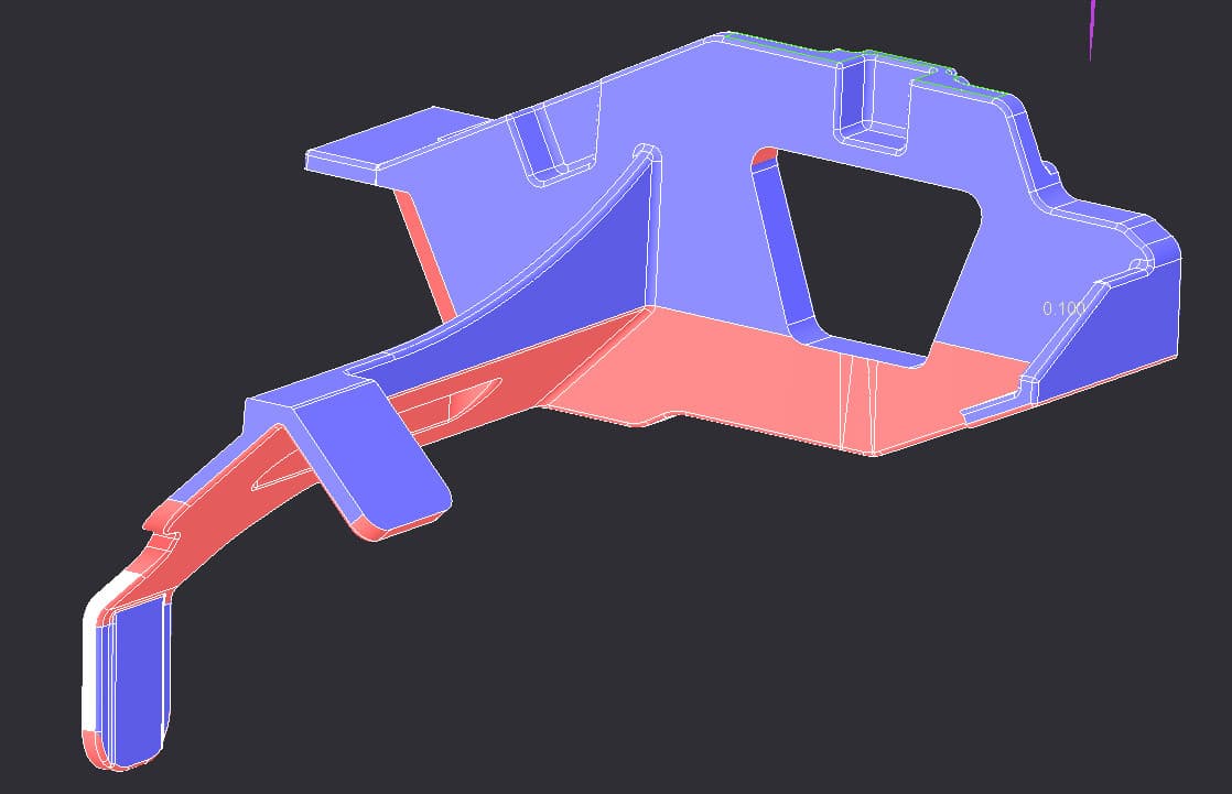
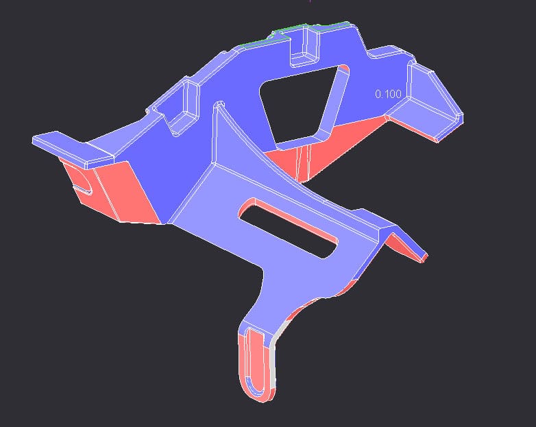
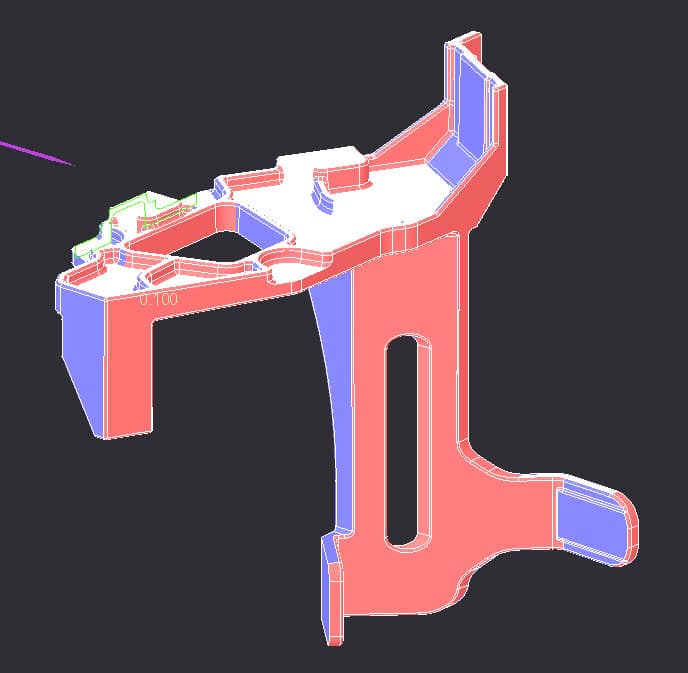
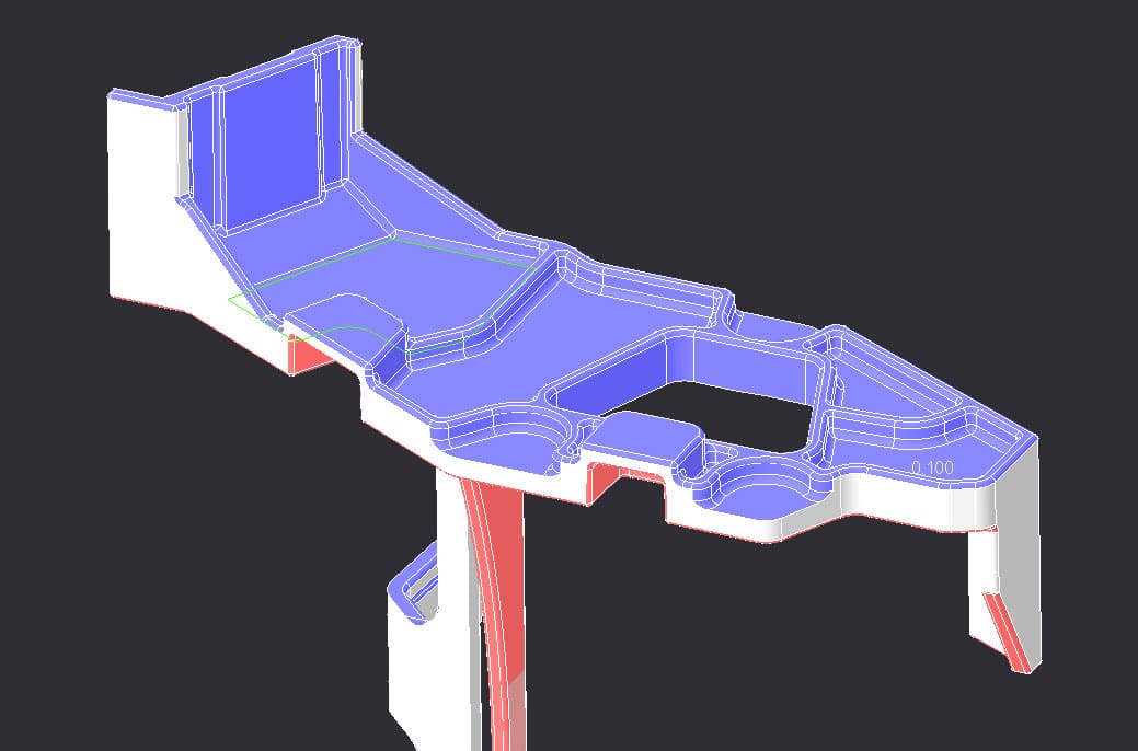
1. It starts with a drawing or 3D CAD Model
Most new casting projects begin when a customer sends us an engineering drawing, CAD model or an existing component they need to manufacture.
At this stage, we’re not simply looking at the dimensions.
Our team needs to understand how the component will ultimately be used.
Important considerations can include:
- Component dimensions and weight
- Required aluminium alloy
- Expected annual quantities
- Batch quantities
- Dimensional tolerances
- Wall thicknesses
- Surface finish requirements
- Machining requirements
- Heat treatment
- Operating environment
- Mechanical requirements
- Critical features and mating surfaces
Understanding these requirements at the beginning of a project helps determine the most appropriate manufacturing route.
2. Design for Manufacture Review
A component that works perfectly on a CAD screen isn’t necessarily optimised for casting.
Before tooling is produced, the design can be reviewed from a manufacturing perspective.
Features such as wall thickness, sharp internal corners, draft angles, ribs, bosses and abrupt changes in section can influence how molten aluminium flows through the mould and how the component solidifies.
Identifying potential problems at this stage can help reduce the risk of defects and unnecessary machining later.
In some cases, relatively small design changes can make a component easier and more economical to manufacture without changing its function.
This is why involving the foundry early in the design process can be valuable.
For more detailed information about designing components for casting, see our Aluminium Casting Design Guide.
3. Choosing the Right Casting Process
Once the component has been reviewed, one of the most important decisions is selecting the appropriate casting process.
At DAC Industries, two of our principal aluminium casting methods are air-set sand casting and gravity die casting.
Air-Set Sand Casting
Sand casting can be particularly suitable for:
- Low and medium production quantities
- Large components
- Complex shapes
- Prototype and development work
- Projects where lower initial tooling investment is desirable
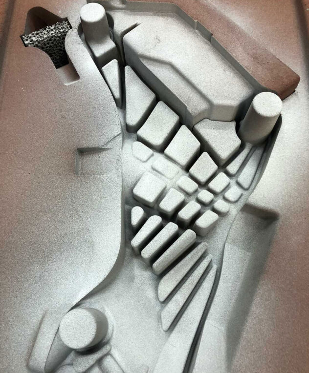
A pattern is used to create the required cavity within the sand mould before molten aluminium is poured into it.
Gravity Die Casting
Gravity die casting uses a reusable metal die rather than a disposable sand mould.
It can be particularly effective for:
- Repeat production
- Medium and higher production volumes
- Components requiring good dimensional consistency
- Improved surface finish
- Projects where tooling investment can be spread across a larger production quantity
The right process isn’t simply determined by component size. Production volume, geometry, required finish, tolerances, and the expected lifetime of the project can all influence the decision.
For a detailed comparison, read our guide to Sand Casting vs Gravity Die Casting.
4. Designing and Manufacturing the Tooling
Once the casting method has been selected and the design approved, tooling can be produced.
This is one of the most important stages of the entire project because the quality and design of the tooling directly influence the consistency of the castings it produces.
For air-set sand casting, tooling may include CNC-machined pattern equipment and core boxes.
Modern 3D CAD data allows the casting geometry to be transferred accurately into the tooling design.
For gravity die casting, reusable metal tooling is produced to form the component. Depending on the design, the tooling may incorporate cores, moving sections and other features required to create the final geometry.
Correctly designed tooling also needs to account for the behaviour of aluminium as it fills the mould and solidifies.
5. Preparing the Mould
The next stage depends on the casting process being used.
For sand casting, the pattern equipment is used to create the mould cavity. Cores may also be introduced where internal passages, recesses or other internal features are required.
For gravity die casting, the reusable metal die is prepared before casting begins.
Careful mould preparation is essential because the quality of the mould has a direct effect on the final casting.
6. Melting and Pouring the Aluminium
With the mould prepared, the selected aluminium alloy is melted and prepared for casting.
The correct alloy is important because different grades of aluminium provide different characteristics, including:
- Strength
- Corrosion resistance
- Machinability
- Wear resistance
- Thermal performance
- Castability
- Response to heat treatment
Temperature and metal quality must be controlled throughout the process.
The molten aluminium is then introduced into the mould, filling the cavity created by the tooling.
As the aluminium cools, it solidifies into the shape of the component.
7. Removing the Raw Casting
Once the aluminium has solidified sufficiently, the casting can be removed.
At this point, the component may look very different from the finished product the customer eventually receives.
The raw casting can still contain runners, risers and excess material associated with the casting process.
These are removed during fettling and finishing.
The casting can then be cleaned and prepared for subsequent manufacturing operations.
8. CNC Machining Critical Features
Casting can create complex near-net-shape components efficiently, but some features may require greater dimensional precision than the casting process alone can provide.
This is where CNC machining becomes part of the manufacturing process.
Typical machined features can include:
- Bores
- Threads
- Bearing locations
- Mounting faces
- Sealing surfaces
- Holes
- Precision mating surfaces
Rather than machining the entire component from a solid billet, casting can create the majority of the geometry before CNC machining is used only where the required tolerances demand it.
This combination can provide an efficient manufacturing solution for many engineering components.
9. Inspection and Quality Control
Before a component enters production or is dispatched to the customer, it needs to meet the agreed requirements.
Inspection may include dimensional checks and other quality-control procedures appropriate to the component and application.
Consistency is particularly important once a component moves into repeat production.
Manufacturing procedures can therefore be documented so that future batches are produced using the same established process.
Material traceability can also form part of the production documentation.
10. The Finished Component
After casting, finishing, machining and inspection, the component is ready for the customer.
What started as a drawing or digital 3D model has now become a physical production component.
From Prototype to Repeat Production
Producing the first successful component is only part of the process.
Once tooling and manufacturing methods have been established, the component can move into repeat production.
Depending on the customer’s requirements, this might mean occasional small batches or ongoing production quantities.
A well-developed casting process should provide consistency from one manufacturing batch to the next while allowing customers to order components according to their production requirements.
What Should You Send a Foundry for a New Casting Project?
Providing good information at the enquiry stage helps a foundry assess your project more accurately.
Where possible, provide:
- 2D engineering drawings
- 3D CAD files
- Required material or aluminium alloy
- Estimated annual quantity
- Expected batch quantities
- Required tolerances
- Machining requirements
- Surface finish requirements
- Heat treatment requirements
- Details about the component’s application
Don’t worry if you don’t have every detail established.
Part of working with an experienced foundry is discussing the manufacturing options and identifying the most appropriate route for the component.
Why Involve Your Foundry Early?
One of the most expensive times to discover a manufacturing problem is after the tooling has already been produced.
Early collaboration gives the foundry an opportunity to identify potential manufacturing issues before significant investment has been made.
This can potentially help:
- Simplify tooling
- Reduce unnecessary machining
- Improve casting consistency
- Reduce the likelihood of defects
- Select a suitable casting process
- Choose an appropriate aluminium alloy
- Reduce manufacturing costs
- Improve production lead times
Casting should therefore be considered during the component design process rather than simply being treated as the final manufacturing step.
Why Involve Your Foundry Early?
At DAC Industries, we support customers throughout the casting manufacturing process — from initial drawings and tooling through to casting, CNC machining, inspection and repeat production.
Our UK foundry works with customers across a wide range of engineering sectors, producing aluminium components using both sand casting and gravity die casting processes.
If you’re developing a new component, replacing an existing casting or looking for an alternative UK foundry, send us your drawing or CAD model.
Our team can review the project and discuss the most appropriate manufacturing route.
Have a casting project you’d like us to look at? Contact DAC Industries and send us your drawing or CAD file for a quotation.


Leave a Reply